 EN


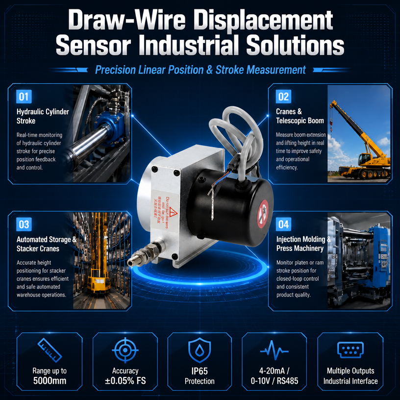
Draw Wire Sensors: A Practical Selection Guide for Industrial Engineers
A draw wire sensor looks simple: a cable, a spring-loaded drum, a sensing element inside. That simplicity is exactly why it gets specified carelessly — and why most field failures are not sensor failures at all. They are range errors, cable-path errors, and output-matching errors that only surface after the machine is commissioned.
This guide walks through the decisions that actually determine whether a draw wire sensor works in your application: measuring range, output signal, linearity and repeatability, environmental protection, and mounting. It also compares draw wire sensors against the three alternatives engineers most often weigh them against.
What a draw wire sensor measures — and what it does not
A draw wire sensor (also called a string potentiometer, cable extension transducer, or yo-yo gauge) converts linear travel into an electrical signal. The measuring cable is attached to the moving object. As the object moves, the cable extends and rotates a drum; the drum drives a sensing element — a precision potentiometer, an encoder, or a magnetic sensing circuit — which produces an output proportional to cable extension.
Three consequences follow directly from that design, and they matter more than any datasheet headline:
It measures cable extension, not the object's true position. The sensor body is fixed to the machine frame. Any flex, thermal expansion, or vibration in that frame becomes measurement error. On long-stroke applications, frame stiffness is often the dominant error source — not the sensor.
It is a single-axis device. The cable must pay out in a straight line. Side-load angle, cable whip, and snatch loads degrade both accuracy and cable life.
It needs a return force. The internal spring retracts the cable. If your application cannot tolerate a few newtons of cable tension, a draw wire sensor is the wrong choice.
Within those constraints, the format is hard to beat: long strokes in a compact body, generous mounting tolerance compared with rod-style sensors, and fast installation on retrofits.
The five specifications that decide whether it works
1. Measuring range — and the reserve you must add
Specify range from actual travel, then add margin. A practical rule is 10–20% headroom above maximum stroke so the cable never reaches its end stop under dynamic overshoot. Running a draw wire sensor to its mechanical limit is the single most common cause of premature failure: the cable is shock-loaded against the stop, and the retraction spring takes the impact.
Check the stated range against how the sensor will actually be mounted. If the cable exits at an angle, the effective stroke the sensor sees is not the stroke of the machine axis — the geometry consumes range.
Also confirm the cable's own length allowance. A sensor rated for 1000 mm of travel may ship with a cable noticeably longer than 1000 mm; that extra length is not usable stroke.
2. Output signal — match it to the control system, not to the catalogue
Four output families cover most industrial requirements:
Output Best for Watch out for
Resistive (potentiometer) Low-cost position feedback, simple analog input cards Input impedance loading; wiper wear over millions of cycles
0–10 V / ±10 V Short cable runs, cabinet-mounted PLC analog cards Voltage drop and noise pickup on long runs
4–20 mA Long cable runs, electrically noisy plants Loop supply and burden resistor budgeting
RS485 / Modbus Multi-sensor networks, digital diagnostics, absolute position Addressing, baud rate, and termination discipline
Choose based on the cable distance to the control cabinet and the noise environment, not on what is in stock. A 0–10 V signal sent 30 m through a drive cabinet will pick up noise that no amount of filtering fully removes; 4–20 mA or RS485 solves it at the specification stage.
For applications where the machine must know position immediately after power-up — without a homing cycle — specify an absolute output rather than a incremental one.
3. Linearity and repeatability are not the same number
Linearity describes how far the output deviates from a straight line across full stroke. Repeatability describes how closely the sensor returns to the same output for the same position. For most control loops, repeatability matters more than linearity: a repeatable but slightly non-linear sensor can be corrected in software; a non-repeatable one cannot.Ask for both figures, and ask whether linearity is stated as ±% of full scale or ±% of reading. On short strokes the difference is significant.
4. Resolution — the number that quietly limits your control
Resolution is the smallest position change the output can distinguish. On resistive and analog-voltage units it is limited by the sensing element and by the electrical noise floor of your input card, not by the sensor alone. A sensor quoted at high resolution feeding a noisy 12-bit input will deliver 12-bit performance.
For slow process positioning (gate opening, level, valve stroke), resolution is rarely the constraint. For high-speed servo or test-bench work, it usually is.
5. Environmental protection and cable path
IP rating protects the housing. It says much less about the cable exit, which is where contamination actually enters. In dust, coolant mist, or washdown environments, confirm how the cable outlet is sealed and whether the cable jacket is compatible with the fluids present.
Temperature matters twice: the sensing element drifts, and the cable and spring change behaviour. If the application runs hot, ask for the compensated temperature range rather than the operating range — they are different numbers.
Draw wire vs. linear potentiometer vs. LVDT vs. magnetostrictive
Draw wire Linear potentiometer (rod style) LVDT Magnetostrictive
Typical stroke ~50 mm to several metres ~10 mm to ~1 m ~1 mm to ~500 mm ~50 mm to several metres
Measuring principle Cable + rotary sensing element Resistive track + wiper Non-contact inductive Non-contact magnetostrictive
Strength Long stroke, small body, easy retrofit Simple, low cost, direct in-line mounting High linearity and repeatability, no wear on the core Absolute output, robust in hydraulic cylinders
Limitation Cable path and tension sensitivity Wiper wear, alignment sensitivity Short stroke, needs a signal conditioner Higher cost, installation constraints
Typical fit Presses, jacks, gates, test rigs, lifters General machine positioning, cost-driven builds Metrology, servo valves, R&D benches Hydraulic cylinders, injection moulding
The decision usually comes down to stroke and mounting space. Beyond roughly a metre of travel, rod-style sensors become long, heavy, and awkward to align — which is where draw wire formats take over. Below a few hundred millimetres, where the highest linearity and wear-free operation matter, an LVDT or a rod-style linear displacement sensor is usually the better engineering answer.
Where draw wire sensors earn their place
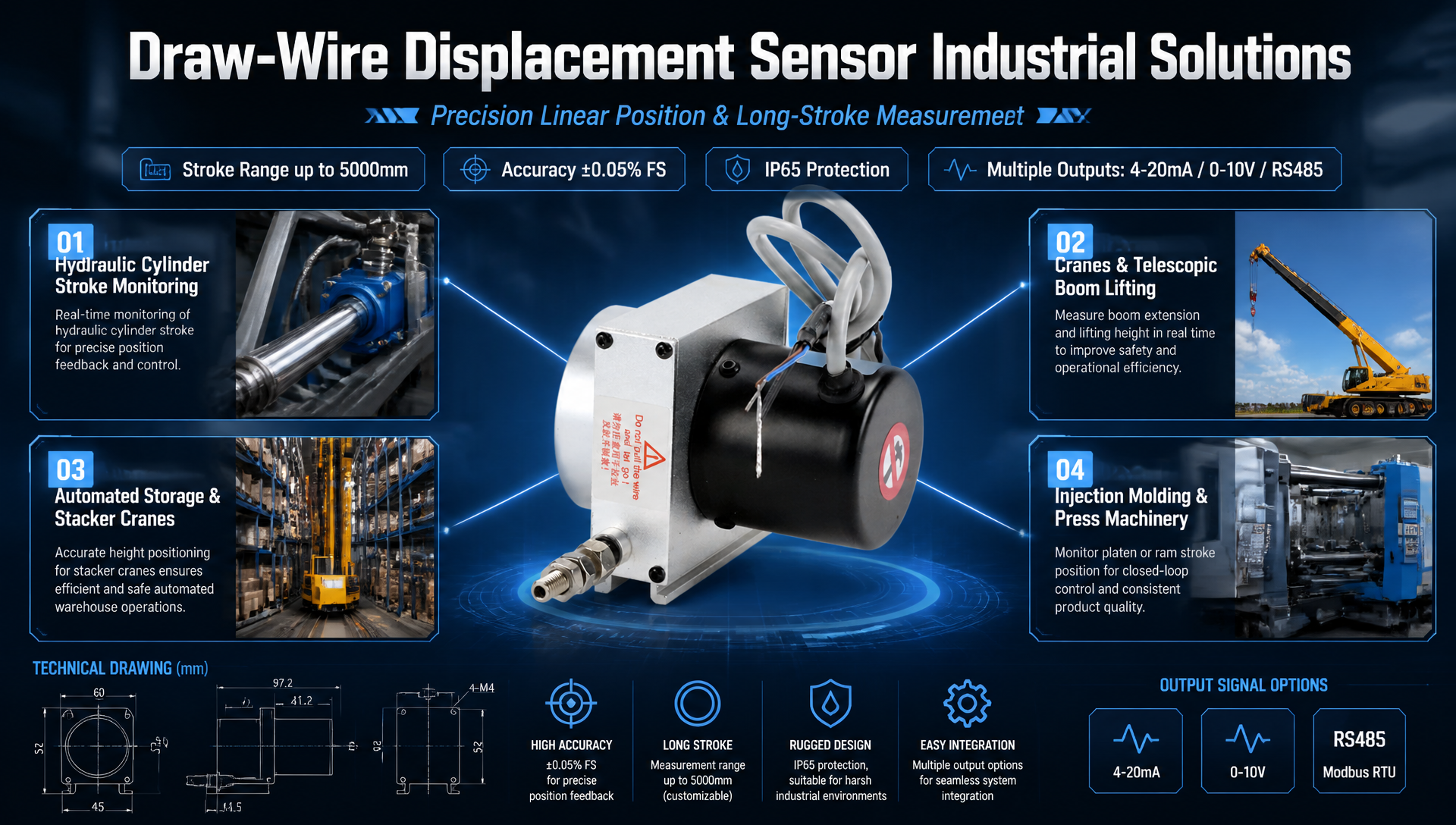
Injection moulding machines. Clamp and ejector position feedback needs a long stroke in a confined space, at cycle rates in the seconds. Draw wire units mount to the frame and follow the moving platen without the rod length a linear potentiometer would require.
Hydraulic jacks and lifting systems. Jack stroke monitoring — including jacks embedded in walls or structures where access is limited — is a classic draw wire job: one anchor point on the frame, one on the moving element, no alignment jig required.
Water conservancy and sluice gates. Gate opening measurement runs to metres of stroke in outdoor conditions. The selection question here is rarely resolution; it is sealing, cable jacket durability, and resistance to silt and humidity.
Test benches and suspension measurement. Spring compression, damper travel, and structural deflection during durability testing demand high repeatability and a cable path that survives vibration. Racing and automotive suspension work is a well-established application for compact draw wire units.
Retrofits. When a machine was never instrumented and there is no room to machine a mounting bore, a draw wire sensor with a bracket often installs in under an hour.
Installation mistakes that cause most field failures
Cable exiting at an angle. Keep the cable path perpendicular to the drum within the manufacturer's stated angle. Even a few degrees of persistent side load wears the cable guide and biases the reading.
A slack or over-tensioned cable. The cable must stay taut through the full stroke. If the axis can move faster than the spring can retract, the cable goes slack and then snaps taut — a shock load that damages the drum.
Mounting the body on a vibrating panel. The sensor measures the relative motion of its two anchor points. A flexible bracket becomes part of the measurement.
Ignoring cable bend radius at the exit. Sharp routing right at the outlet fatigues the jacket and eventually the conductors.
No strain relief on the electrical cable. The signal cable is not a mechanical member; tying it to moving parts transmits load into the connector.
Commissioning without a full-stroke sweep. Run the axis slowly from end to end and watch the output for dropouts, jumps, and mechanical interference before production starts.
For long-stroke outdoor installations, add a physical end stop that is independent of the sensor. The sensor should never be the mechanical limit of the machine.
Integrating with the control system
Three integration details are worth settling before you order:
Input impedance. A resistive output forms a voltage divider with the input card. If the card's impedance is not significantly higher than the sensor's track resistance, the reading will be compressed at one end of the stroke. Check this before blaming the sensor.
Cable length and shielding. For analog voltage outputs, keep runs short and use shielded twisted pair with the shield grounded at one end. For long runs, switch to current loop or digital output.
Scaling and calibration. Decide at design time whether the PLC will scale raw counts or engineering units, and document the calibration points. A two-point calibration at 10% and 90% of stroke avoids the end-stop regions where mechanical tolerances are worst.
Maintenance and lifecycle
Draw wire sensors are consumables in the same sense as a belt or a filter — the cable and spring have a finite cycle life, and the specification should reflect that. In continuous production, plan for periodic inspection of cable condition, retraction force, and output repeatability at a reference position. A repeatability check at one fixed point, logged monthly, will catch degradation long before it becomes a quality escape.
Where cycle life is the binding constraint, specify the sensing element for it: a potentiometer-based unit and an encoder-based unit have very different wear profiles at the same stroke and speed.
FAQ
What is the difference between a draw wire sensor and a string potentiometer? They are the same device under different names. "String potentiometer" and "cable extension transducer" are common in North America; "draw wire sensor" and "draw wire encoder" are more common in Europe and Asia.
Can a draw wire sensor measure speed as well as position? Yes — differentiate the position signal, provided the output is clean and the sampling rate is adequate. For high-accuracy velocity work, confirm the resolution and update rate first; velocity accuracy is derived from position accuracy.
How accurate is a draw wire sensor? Accuracy depends on stroke length, sensing element, and — critically — mounting stiffness. On short strokes with a rigid frame, precision units are highly repeatable. On multi-metre strokes, frame deflection and cable sag commonly dominate the error budget.
Can it be used outdoors? Yes, with the right IP rating and cable jacket. The limiting factors outdoors are usually UV exposure of the cable, water ingress at the cable exit, and temperature swing rather than the sensing element itself.
Is a draw wire sensor suitable for a hydraulic cylinder? It can be, mounted externally alongside the cylinder. If the cylinder must be instrumented internally, a magnetostrictive or in-cylinder LVDT design is usually the more practical route.
What stroke reserve should I allow? Plan for 10–20% above maximum working stroke, and make sure the machine's hard stop — not the sensor — defines the mechanical limit.
Choosing the right format for your stroke
The draw wire format wins where stroke is long, mounting space is short, and installation speed matters. It loses where the frame is flexible, the cable path cannot be kept straight, or wear-free operation at very high cycle counts is the priority. Getting that decision right at the specification stage costs an hour; getting it wrong costs a commissioning window.
If you are specifying a displacement sensor for a press, jack, gate, test rig, or production machine and want a second opinion on range, output signal, and mounting, our engineering team can review your application and recommend a format — draw wire sensors, linear displacement sensors, LVDT sensors, and magnetostrictive sensors are all manufactured in-house, so the recommendation is not limited to one technology.
Talk to an engineer about your application → Request a quote