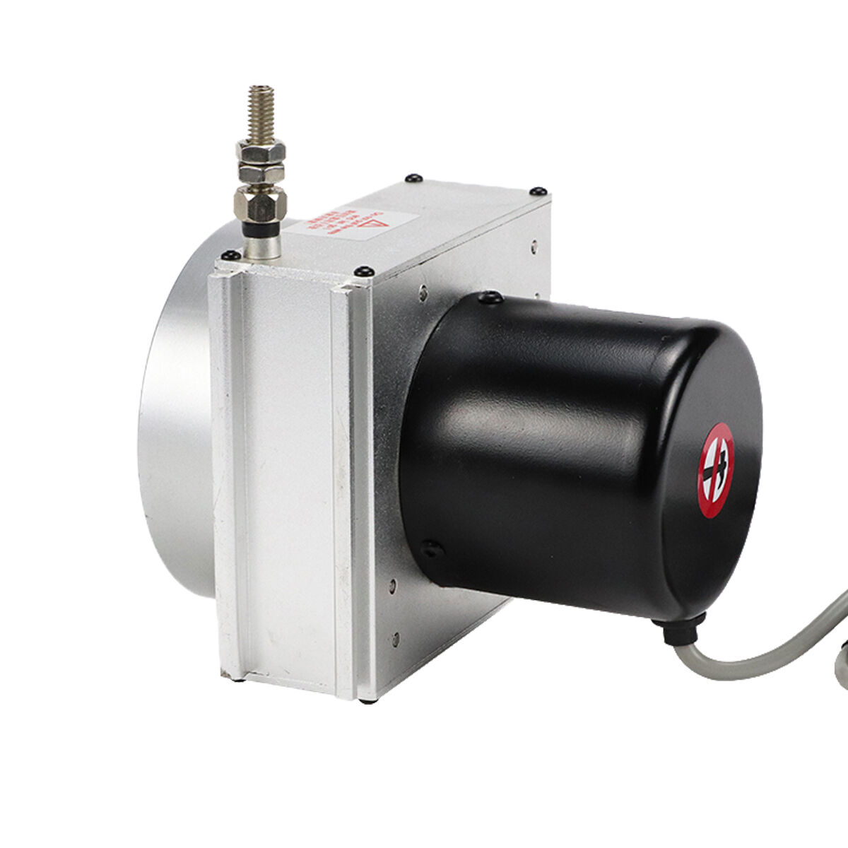
Heavy equipment operations demand precise positioning and measurement systems to ensure optimal performance and safety. A draw wire sensor represents one of the most reliable solutions for monitoring linear displacement in challenging industrial environments. These sophisticated devices provide accurate position feedback for hydraulic cylinders, boom arms, and other moving components that require continuous monitoring. Understanding the critical design considerations for proper installation ensures maximum performance, longevity, and measurement accuracy in demanding applications.
Environmental Protection Requirements
Ingress Protection Standards
Heavy equipment operates in harsh environments where dust, moisture, and debris present constant challenges to sensitive electronic components. When selecting a draw wire sensor for industrial applications, the ingress protection rating becomes a critical specification that directly impacts long-term reliability. IP67 or higher ratings ensure complete protection against dust ingress and temporary water immersion, which commonly occurs during equipment washing or operation in wet conditions. The sensor housing must withstand high-pressure water jets and resist corrosion from chemical exposure typical in construction, mining, and agricultural environments.
Temperature fluctuations in heavy equipment applications can range from extreme cold during winter operations to intense heat generated by hydraulic systems and engine compartments. A properly specified draw wire sensor must maintain accuracy across the entire operating temperature range while compensating for thermal expansion effects. Advanced sensors incorporate temperature compensation algorithms that automatically adjust readings to maintain precision regardless of ambient conditions. This feature becomes particularly important for applications requiring sub-millimeter accuracy over extended measurement ranges.
Vibration and Shock Resistance
Heavy machinery generates significant vibration and shock forces that can damage sensitive measurement components if not properly addressed during installation planning. The draw wire sensor mounting system must isolate the device from excessive mechanical stress while maintaining rigid positioning for accurate measurements. Vibration dampening mounts and flexible coupling systems help protect internal components from fatigue failure caused by constant oscillation. Proper cable routing and strain relief become essential elements that prevent wire breakage and maintain signal integrity throughout the equipment's operational life.
Impact resistance specifications must align with the expected shock loads encountered during normal equipment operation. Construction and mining equipment frequently experience sudden directional changes, emergency stops, and collision forces that create severe acceleration spikes. The sensor housing and internal mechanisms must withstand these forces without losing calibration or suffering permanent damage. Robust construction techniques and protective mounting configurations ensure reliable operation even under the most demanding conditions.
Mechanical Installation Considerations
Mounting Configuration and Alignment
Proper mounting alignment significantly influences measurement accuracy and sensor longevity in heavy equipment applications. The draw wire sensor must be positioned to ensure the measurement cable travels in a straight line without binding or excessive side loading during the full range of motion. Angular misalignment creates additional friction forces that accelerate cable wear and reduce measurement precision. Installation guidelines typically specify maximum allowable angular deviation, usually within two degrees of perpendicular alignment to the direction of travel.
Mounting bracket design must accommodate thermal expansion and equipment deflection without introducing measurement errors or mechanical stress. Heavy equipment frames experience significant flexing under load, and mounting systems must account for these dynamic changes. Flexible mounting arrangements that maintain proper sensor alignment while allowing for structural movement prevent binding and premature failure. The mounting hardware must also provide sufficient strength to handle the forces generated during emergency stops or sudden direction changes.
Cable Management and Protection
The measurement cable represents one of the most vulnerable components in a draw wire sensor installation, requiring careful attention to routing and protection systems. Cable guides and protective conduits shield the wire from sharp edges, moving components, and environmental hazards that could cause premature failure. Proper routing prevents cable entanglement with other equipment components while maintaining the minimum bend radius specified by the manufacturer. Cable tension adjustments ensure smooth operation without excessive slack that could cause binding or tangling.
Strain relief connections at both the sensor housing and the attachment point prevent cable damage from repeated flexing and tension cycles. High-quality installations incorporate progressive strain relief systems that gradually distribute mechanical stress over a longer cable length. This approach significantly extends cable life compared to installations with abrupt stress concentration points. Regular inspection schedules should include cable condition assessment to identify wear patterns and schedule preventive replacements before failure occurs.
Electrical Integration and Signal Processing
Power Supply and Signal Conditioning
Heavy equipment electrical systems present unique challenges for draw wire sensor integration, including voltage fluctuations, electrical noise, and electromagnetic interference from high-current components. Proper power supply filtering and regulation ensure stable sensor operation despite variations in the main electrical system. Isolated power supplies prevent ground loops and reduce noise interference that could affect measurement accuracy. The sensor's power requirements must match the available electrical capacity while considering the additional load on the equipment's charging system.
Signal conditioning circuits process the raw sensor output to provide compatible signals for control systems and data logging equipment. Modern draw wire sensor installations often include digital signal processing capabilities that enhance measurement resolution and reduce noise sensitivity. Programmable output scaling allows the sensor to interface directly with various control system input requirements without additional signal conversion hardware. This integration simplification reduces installation complexity and improves system reliability.
Communication Protocol Compatibility
Advanced heavy equipment systems increasingly rely on digital communication networks for sensor data transmission and system integration. The draw wire sensor must support communication protocols compatible with the existing equipment control architecture. Common industrial protocols include CAN bus, Modbus, and proprietary manufacturer-specific systems that require careful interface design. Protocol compatibility ensures seamless integration with existing diagnostic systems and enables remote monitoring capabilities for fleet management applications.
Data transmission reliability becomes critical in applications where position feedback directly controls equipment safety systems or operational functions. Redundant communication paths and error detection algorithms prevent data corruption that could lead to equipment malfunction or safety hazards. Real-time monitoring capabilities allow operators to detect sensor degradation before complete failure occurs, enabling scheduled maintenance that prevents unexpected downtime.
Calibration and Accuracy Considerations
Initial Setup and Configuration
Proper calibration procedures ensure that the draw wire sensor provides accurate position measurements throughout its operational range. Initial setup requires establishing reference positions and scaling factors that translate sensor output to meaningful engineering units. Multi-point calibration techniques verify accuracy across the entire measurement range and identify any non-linearity that requires compensation. Documentation of calibration procedures and reference measurements enables consistent maintenance practices and troubleshooting support.
Environmental factors during calibration must match typical operating conditions to ensure measurement accuracy in real-world applications. Temperature, humidity, and mechanical loading conditions can influence sensor behavior and should be considered during the calibration process. Advanced calibration procedures include temperature compensation adjustments that maintain accuracy across the expected operating temperature range. Regular recalibration schedules help maintain measurement precision and identify gradual drift that could indicate component aging or environmental damage.
Accuracy Validation and Maintenance
Ongoing accuracy validation ensures that the draw wire sensor continues to meet application requirements throughout its service life. Comparative measurements using independent reference standards help identify calibration drift and verify measurement precision. Statistical analysis of measurement data can reveal systematic errors or random variations that indicate component degradation or installation problems. Automated validation routines integrated into the equipment control system provide continuous monitoring and alert operators to potential accuracy issues.
Preventive maintenance procedures specific to draw wire sensor installations help maintain optimal performance and extend service life. Regular cleaning of the sensor housing and cable guides prevents debris accumulation that could affect operation. Lubrication of moving components according to manufacturer specifications reduces friction and wear. Cable tension adjustments compensate for stretching and ensure smooth operation throughout the measurement range. These maintenance activities should be integrated into standard equipment service schedules to ensure consistent execution.
Safety and Compliance Factors
Functional Safety Requirements
Heavy equipment applications often require compliance with functional safety standards that govern the design and implementation of safety-related systems. When a draw wire sensor provides position feedback for safety-critical functions, the installation must meet specific reliability and fault detection requirements. Redundant sensor configurations and diagnostic capabilities help achieve the required safety integrity levels for critical applications. Failure mode analysis identifies potential sensor faults and their impact on equipment safety systems.
Safety system integration requires careful consideration of sensor failure modes and their effect on equipment operation. Fail-safe design principles ensure that sensor failures result in safe equipment states rather than hazardous conditions. Position monitoring systems must include provisions for detecting sensor faults and initiating appropriate safety responses. Regular testing of safety functions verifies that the draw wire sensor installation continues to meet safety requirements throughout its service life.
Regulatory Compliance and Certification
Industry-specific regulations may impose additional requirements on draw wire sensor installations in heavy equipment applications. Mining equipment, for example, must comply with explosion-proof requirements in potentially hazardous atmospheres. Construction equipment operating on public roads must meet transportation regulations that could affect sensor installation and operation. Understanding applicable regulations during the design phase ensures compliance and prevents costly modifications later in the project.
Third-party certification and testing provide independent verification that the draw wire sensor installation meets required standards and specifications. Certified products have undergone rigorous testing to verify performance, safety, and reliability characteristics. Documentation of certification and compliance helps satisfy regulatory requirements and provides assurance to equipment operators and maintenance personnel. Regular compliance audits ensure continued adherence to applicable standards and regulations.
Performance Optimization Strategies
Resolution and Response Time Enhancement
Maximizing draw wire sensor performance requires optimization of both measurement resolution and response time characteristics. Higher resolution sensors provide more precise position feedback but may require additional signal processing that increases response time. Application requirements must balance these competing factors to achieve optimal system performance. Dynamic response characteristics become particularly important for control applications that require rapid position feedback for stable operation.
Signal filtering techniques can improve measurement stability by reducing noise and vibration effects while maintaining adequate response time for control applications. Adaptive filtering algorithms automatically adjust filtering parameters based on operating conditions to optimize performance. Digital signal processing capabilities enable sophisticated filtering and compensation techniques that were not possible with analog sensor systems. These advances allow draw wire sensor installations to achieve higher accuracy and reliability in challenging heavy equipment environments.
Integration with Advanced Control Systems
Modern heavy equipment increasingly incorporates advanced control systems that can leverage enhanced draw wire sensor capabilities for improved operational efficiency. Predictive algorithms use position feedback to optimize equipment operation and reduce fuel consumption. Automated control functions rely on precise position feedback to implement complex operational sequences safely and efficiently. The sensor installation must support these advanced features while maintaining compatibility with basic operational requirements.
Data logging and analysis capabilities enable continuous improvement of equipment performance and maintenance practices. Historical position data can reveal usage patterns and identify opportunities for operational optimization. Trend analysis helps predict maintenance requirements and schedule service activities to minimize downtime. Remote monitoring capabilities allow fleet managers to optimize equipment utilization and identify training opportunities for operators. These advanced features require careful consideration during the initial draw wire sensor installation to ensure compatibility and optimal performance.
FAQ
What cable length limitations should be considered for draw wire sensor installations
Cable length limitations depend on the specific draw wire sensor model and application requirements, but typical installations can accommodate measurement ranges from 50 millimeters to over 50 meters. Longer cable lengths may require larger sensor housings and more robust cable construction to handle the increased weight and tension forces. The maximum extension speed must also be considered, as high-speed applications may require shorter cables to prevent dynamic loading that could cause premature failure. Consult manufacturer specifications for specific cable length limitations and recommended installation practices.
How does cable tension affect draw wire sensor accuracy and longevity
Proper cable tension significantly impacts both measurement accuracy and sensor longevity in heavy equipment applications. Excessive tension creates additional stress on internal components and can cause premature cable failure, while insufficient tension may result in cable slack that affects measurement precision. Most draw wire sensor installations include adjustable tension mechanisms that allow optimization for specific applications. Regular tension adjustments during maintenance help compensate for cable stretching and ensure optimal performance throughout the sensor's service life.
What environmental sealing requirements are necessary for outdoor heavy equipment applications
Outdoor heavy equipment applications require draw wire sensor installations with robust environmental sealing to protect against water ingress, dust contamination, and temperature extremes. IP67 or IP68 ratings provide adequate protection for most applications, while specialized sealing may be required for underwater or chemical exposure scenarios. Cable entry points and connector interfaces represent the most vulnerable areas and require careful attention to sealing integrity. Regular inspection and maintenance of sealing components help maintain environmental protection throughout the sensor's operational life.
How should cable routing be planned to prevent interference with equipment operation
Cable routing for draw wire sensor installations must consider the full range of equipment motion and potential interference with other components or operational activities. The cable path should avoid sharp edges, moving parts, and high-temperature areas that could cause damage or premature failure. Protective conduits and cable guides help maintain proper routing while allowing for equipment flexing and movement. Installation drawings should document the recommended cable routing to ensure consistent installation practices and facilitate future maintenance activities. Regular inspection of cable routing helps identify potential problems before they result in sensor failure or equipment interference.
Table of Contents
- Environmental Protection Requirements
- Mechanical Installation Considerations
- Electrical Integration and Signal Processing
- Calibration and Accuracy Considerations
- Safety and Compliance Factors
- Performance Optimization Strategies
-
FAQ
- What cable length limitations should be considered for draw wire sensor installations
- How does cable tension affect draw wire sensor accuracy and longevity
- What environmental sealing requirements are necessary for outdoor heavy equipment applications
- How should cable routing be planned to prevent interference with equipment operation